CoaXPress Cable Length
What is the maximum cable length I can use in my system?
CoaXPress Cable lengths considerations
The CoaXPress standard is a well-known high-speed interface designed to transport, using a single coaxial cable, a high-speed data downstream (typically from a camera to a frame grabber), low-speed control data and DC power (from the frame grabber to the camera). It was first released in 2010 and until this day, one of the most recurrent questions from customers and adopters is “What is the maximum cable length I can use in my system?” and the answer for this question is usually “It depends…”.
This article will try to answer this question by introducing fundamental characteristics of coaxial cables that influence their maximum reachable distance, the impact of these characteristics from the point of view of the CoaXPress standard, and finally what the solutions are to go beyond the standard limits.
Coaxial Cables: Attenuation vs. Frequency
Coaxial cables, or coax for short, were designed in the 19th century to eliminate signal interference between parallel cables. Modern coaxial cables are widely used to transmit and receive high frequency electrical signals in a large spectrum of applications going from radio stations to highspeed computer systems.
The main characteristic of coaxial cables that limits their maximum length is the signal attenuation along the cable. Usually expressed in decibels per 100 ft or 100 m (dB / 100 ft or dB / 100 m), the cable attenuation is frequency dependent, in other words, it varies in function of the frequency being transmitted.
In the graphic below we can see typical Attenuation vs. Frequency curves from four different cables targeting the same application domain. These curves are usually provided by the cable makers where the attenuation is measured at the frequencies used in the target application domain of the cable.
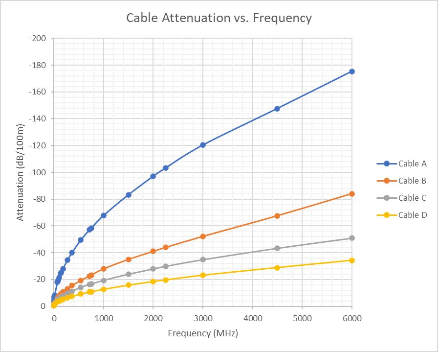
In the graph above, cable A is a thin and light cable with a diameter of only 2.5 mm; it presents the highest attenuation of the four. Cables B and C have the same external diameter of 7 mm but with different mechanical characteristics. Cable B is built to be flexible, targeting applications where cables are exposed to several bending cycles during operation. Cable C is a more regular cable used in fixed installations with limited bending cycles. Cable D is a thick and heavy cable with an external diameter of 10 mm; it globally offers low signal attenuation.
| Cable Type | Cable Diameter (mm) | Mechanical Characteristic | Attenuation (comparison) |
|---|---|---|---|
| Cable A | 2.5 | Rigid (single core) | – – – – |
| Cable B | 7 | Flexible (stranded core) | – – – |
| Cable C | 7 | Rigid (single core) | – – |
| Cable D | 10 | Rigid (single core) | – |
To obtain the maximum cable length that we can use in a system, we must know the maximum signal attenuation allowed by the system’s receiver. For example, in a system where the signal attenuation allowed by the receiver is -17 dB at 3000 MHz, we can simply cross-multiply the known cable attenuation at the target frequency by the maximum allowed signal attenuation, which in this case is -17 dB. Computing the maximum cable length at 3000 MHz for Cables A, B, C, and D, we obtain the following:
| Cable Type | Cable Attenuation (dB/100m) | Target Frequency (MHz) | Max. Signal Attenuation (dB) | Max. Cable Length (m) |
|---|---|---|---|---|
| Cable A | -120 | 3000 | -17 | 14.2 |
| Cable B | -52 | 32.7 | ||
| Cable C | -35 | 48.6 | ||
| Cable D | -23 | 73.9 |
As we can see in this example, the answer “It depends…” is still the right one. The signal attenuation along the cable strongly depends on several factors like the diameter of the coax core conductor, if it is made of a single rigid copper conductor or stranded for better flexibility, its quality, and the insulation materials. For a quick analysis purpose, we can say that thin and light cables have higher signal attenuation resulting in shorter cable reach, while thick and heavy cables have lower signal attenuation, thus longer cable reach. When cables have similar quality and diameter, the attenuation can vary in function of their mechanical characteristics:
- More flexibility (stranded core) = more attenuation
- Less flexibility (rigid core) = less attenuation
Cable Length in the CoaXPress Standard
As discussed before, to calculate the maximum cable length at a given frequency, we must know the maximum attenuation allowed by the system receiver at that frequency and the corresponding signal attenuation in the cable. The CoaXPress standard not just defines the maximum signal attenuation allowed at the receiver side but also the maximum attenuation allowed for cables. The reason for that is to improve the user experience by allowing cable manufacturers to certify off-theshelf products that can interoperate with any other CoaXPress certified product like cameras and frame grabbers. The table below shows the maximum allowed high-speed signal attenuation for receivers and cables:
| CoaXPress Speed | Bit Rate (Gbps) | Frequency (GHz) | Attenuation @ Receiver (dB) | Attenuation @ Cable (dB) |
|---|---|---|---|---|
| CXP-1 | 1.250 | 0.625 | -22.0 | -21.2 |
| CXP-2 | 2.500 | 1.250 | -27.2 | -26.0 |
| CXP-3 | 3.125 | 1.5625 | -28.1 | -26.8 |
| CXP-5 | 5.000 | 2.500 | -22.6 | -20.9 |
| CXP-6 | 6.250 | 3.125 | -17.8 | -15.8 |
| CXP-10 | 10.000 | 5.000 | -23.4 | -20.8 |
| CXP-12 | 12.500 | 6.250 | -20.9 | -17.9 |
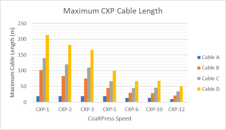
The difference between the maximum attenuation for receiver and cables creates a security margin where cables must be a few meters shorter than the maximum length acceptable by the receiver. This margin guarantees that any CoaXPress certified off-the-shelf cable will interoperate with certified frame grabbers and cameras. If we go back to the example of Cables A, B, C, and D, we obtain the following maximum lengths:
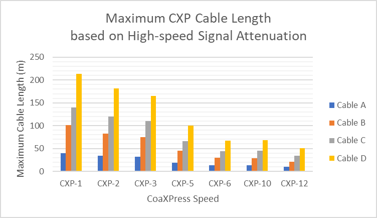
Here we can see that the answer “It depends…” is again the right one. If we take Cable C for example, it can have up to 34 m in a CXP-12 system, while in a CXP-3 system the same cable can reach up to 110 m! This shows that system parameters can also influence the maximum cable length supported.
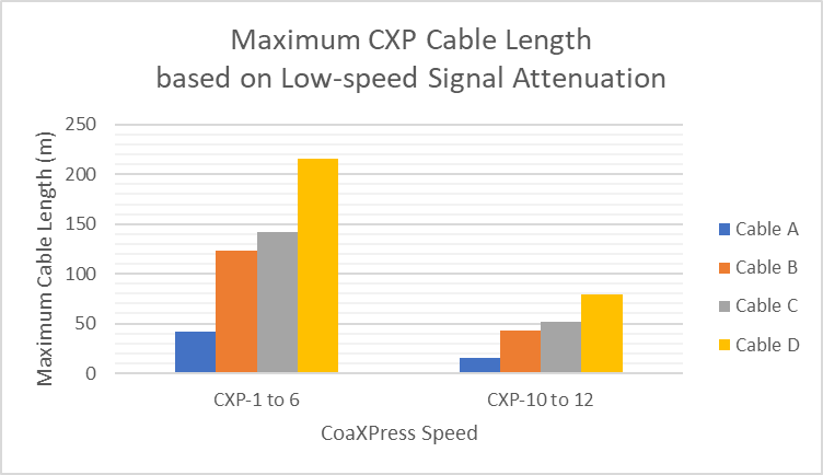
The CoaXPress standard also defines the maximum allowed attenuation for the low-speed signals used for camera control (upstream from frame grabber to the camera). The table below shows the maximum allowed low-speed signal attenuation for receivers and cables:
| CoaXPress Speed | Bit Rate (Mbps) | Frequency (MHz) | Attenuation @ Receiver (dB) | Attenuation @ Cable (dB) |
|---|---|---|---|---|
| CXP-1 to 6 | 20.833 | 30 | -4.9 | -4.74 |
| CXP-10 to 12 | 41.666 | 60 | -2.6 | -2.5 |
For example with Cables A, B, C, and D, the attenuation of low-speed signals has no impact on the maximum cable length since these parameters provide longer cables than the ones based on the high-speed attenuation parameters. As in CoaXPress both high-speed and low-speed signals are present in the same cable, the cable length will be limited by the smallest result. The graph below shows the results using the maximum allowed low-speed signal attenuation parameters:
Besides the signal attenuation along the cable, the cable length in CoaXPress can also be influenced by the round-trip DC resistance of the cable. The reason for that is the CoaXPress possibility to power the camera via the same coaxial cable used for data transfer. This feature called Power over CoaXPress (PoCXP) has a voltage drop budget of 3.5 V for a maximum current of 703 mA, which gives a maximum round-trip DC resistance of 4.98 Ω.
When we apply this parameter on Cables A, B, C, and D, we obtain the following maximum cable lengths:
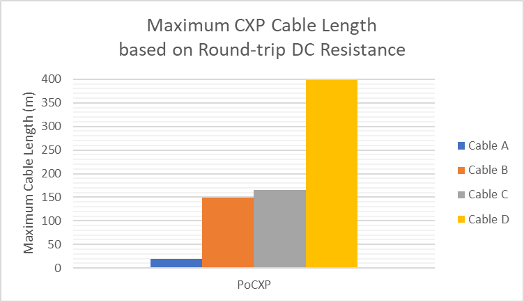
These results show that the DC resistance is more important for thin cables like Cable A. Since DC resistance is the same at all CXP speeds, the maximum length for Cable A will be limited to 19 m while for Cables B, C, and D, the DC resistance have no influence.
Finally, we can obtain the following maximum cable length graph using all results from the cable attenuation for high- and low-speeds and round-trip DC resistance:
Also, regarding the CoaXPress standard, a common misunderstanding is the maximum cable length given as an example in the standard document. The CoaXPress standard uses the Belden 1694A as reference in the document to illustrate the impact of the required parameters on the cable length. Many readers take the results for the Belden 1694A as the absolute maximum cable length for CoaXPress, while, as we have seen in this article, it is just the result for one specific cable.
Off-the-shelf CoaXPress Cables
In practice, CoaXPress users don’t need to carry out the analysis of cable length as presented here. Several companies provide off-the-shelf cable assemblies respecting the CoaXPress standard requirements. Many of these companies also certify their cables by the Japan Industrial Imaging Association (JIIA) which hosts the CoaXPress standard. This certification guarantees the interoperability of all CoaXPress components (Cameras, Frame Grabbers, and Cables).
Here you can find a list of companies providing off-the-shelf CoaXPress cables:
Going Beyond the Standard Limits
CoaXPress Equalizers Gen2
With the introduction of CXP-10 and CXP-12 speeds in CoaXPress standard v2.0, Camera and Frame Grabber manufacturers had access to higher speed-grade components like cable drivers and equalizers to be able to reach up to 12.5 Gbps. This second generation of components has a better sensitivity to retrieve the serial data from highly attenuated signals. A side effect of this new generation of components is that we can support longer cables at CXP-1 to CXP-6 speeds in comparison with the first generation of CoaXPress equalizers. Euresys, for example, has validated systems running at CXP-6 over second-generation equalizers with 72 m of cable, which is 140 % more cable length than it is defined by the CoaXPress Standard.
The reason for the difference between the maximum attenuations defined at CoaXPress standard for CXP-1 to CXP-6 speeds and the ones obtained with second-generation components is due to the off-the-shelf experience proposed by CoaXPress. A certified CoaXPress cable must interoperate with any generation of CoaXPress components and in the case of the example with 72 m of cable at CXP-6, the same cable is not supported by first-generation CoaXPress equalizers.
Systems that leverage the better sensitivity of second-generation components must employ custom cables instead of off-the-shelf ones. These custom cables require functional validation by the system integrators along with the camera and frame grabber manufacturers.
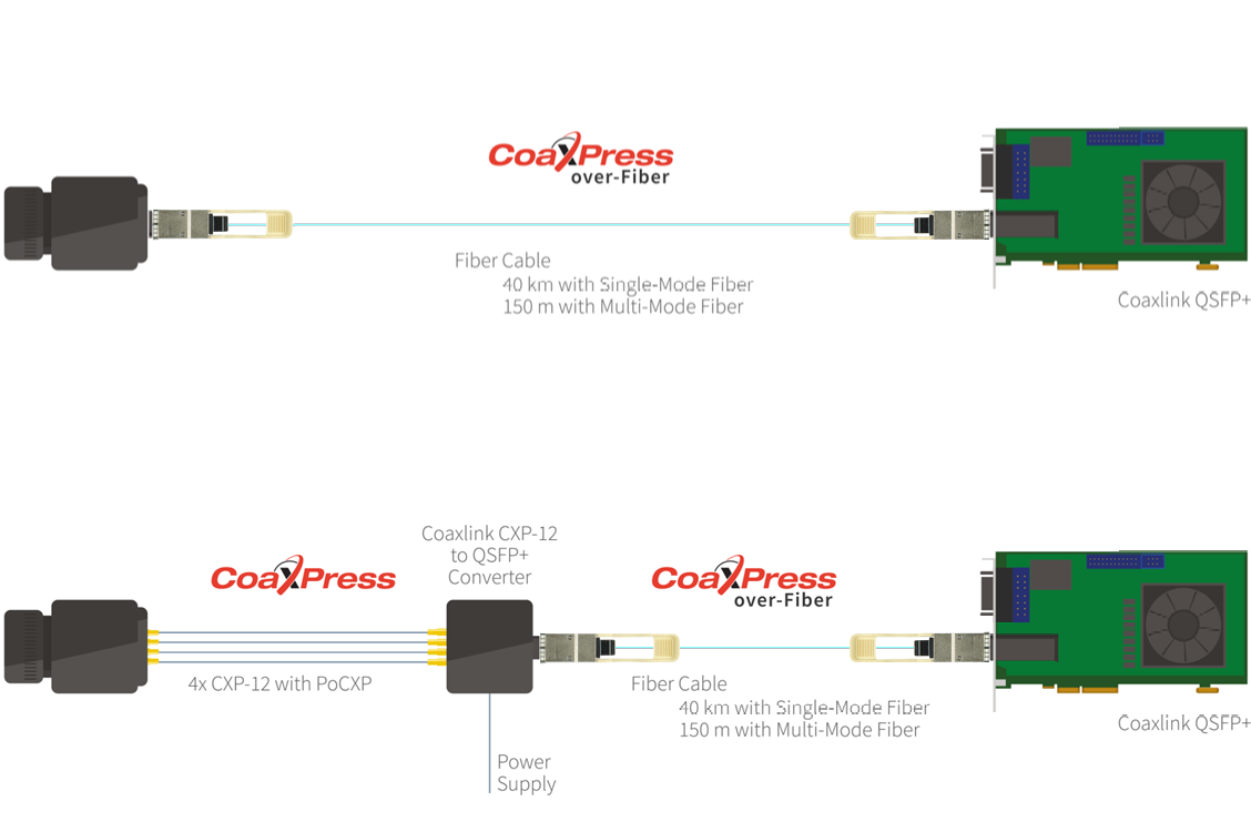
CoaXPress-over-Fiber
The most economical solution for long distances is to use fiber optics as transmission medium.
Fiber cables are much lighter, thinner, less expensive than coax cables, and can deliver very high bandwidths over very long distances.
With the introduction of CoaXPress-over-Fiber as an extension of the CoaXPress standard, we have an easy solution to go beyond the cable lengths for coax as defined in the standard. Note that the use of fiber has other advantages like less cable congestion, EMI immunity, and higher speeds, but these topics are out of the scope of this article. Note also that it is not possible to supply power via fiber cables as in the case of PoCXP via coax cables.
There are two fiber solutions to go beyond the maximum lengths of coax cables. The first one is a system fully based on the CoaXPress-over-Fiber standard where both camera and frame grabber are compliant with the standard and interconnected directly via fiber. The second solution is via a converter that can interface a CoaXPress camera based on coax cables to a CoaXPress-over-Fiber frame grabber. Both solutions allow us to use the full range of fiber cable lengths, going from few meters to tens of kilometers.